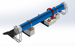
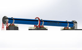
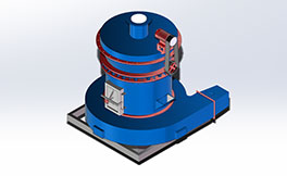
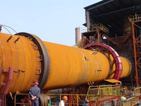
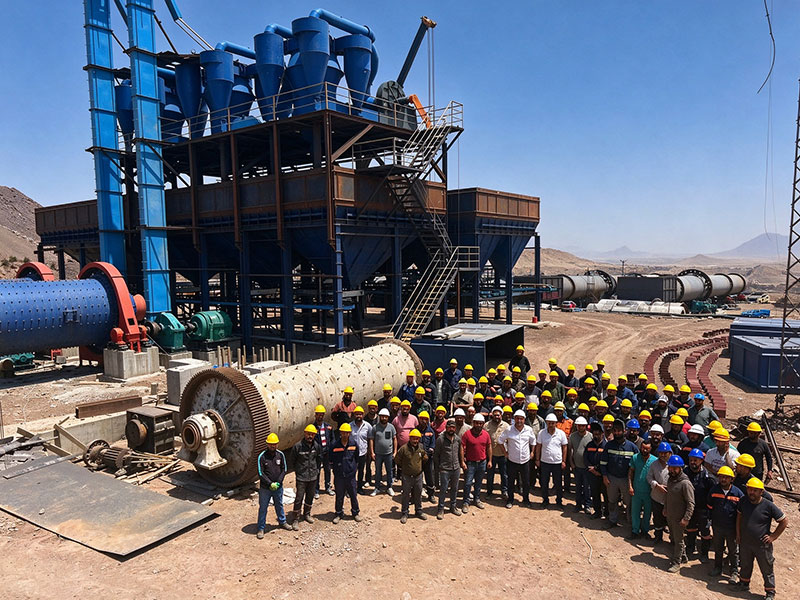
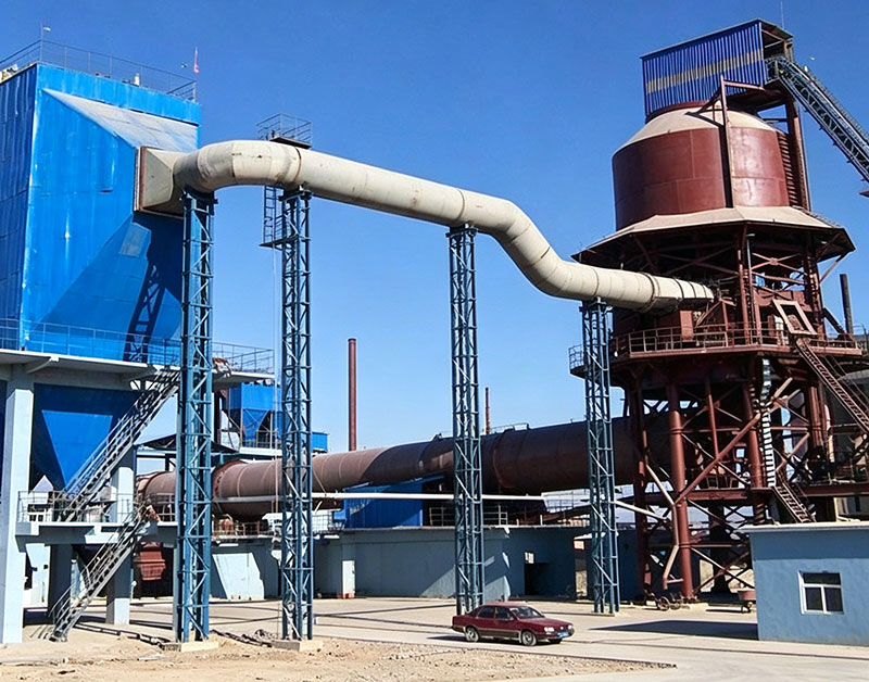
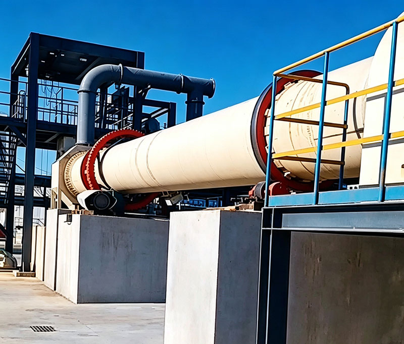
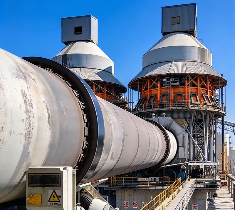
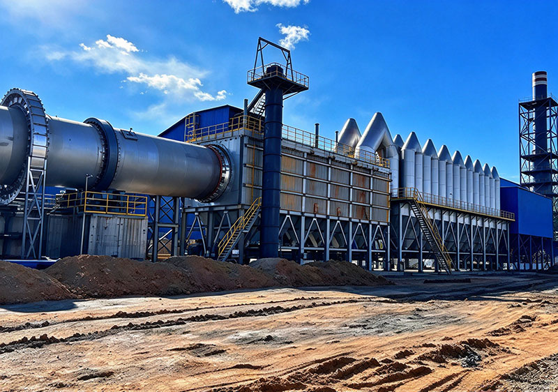
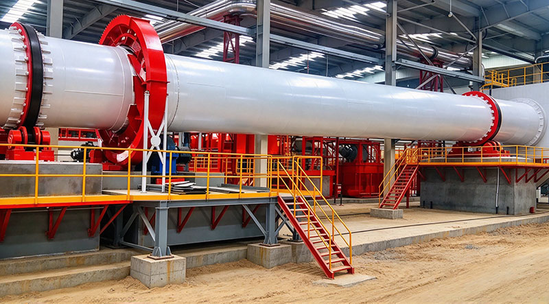
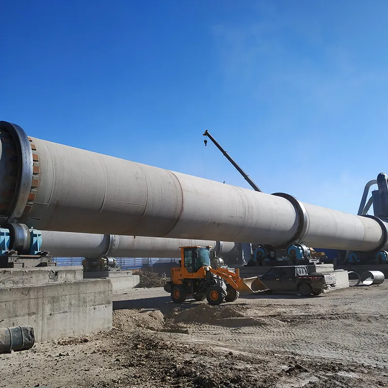
Oil Fracturing Proppant Rotary Kiln is currently the most ideal calcining equipment for the processing of petroleum proppant technology, and it is also one of the most critical process steps. Its main advantages include: large production capacity, easy controllability, strong operability, and suitability for calcining various specifications of ceramic sand. In view of the specific characteristics of ceramic sand, our company has developed and produced this rotary kiln, and has continuously improved the product by addressing the shortcomings identified in actual production, making the product increasingly refined. This effectively ensures the calcining quality of petroleum proppants. Petroleum fracturing proppant, commonly known as petroleum proppant or ceramic sand, is a ceramic granular product with high fracturing strength. It is mainly used for downhole support in oilfields to increase the production of oil and natural gas, and is classified as an environmentally friendly product. This product is made from high-quality bauxite, coal, and various other raw materials through ceramic sintering. It serves as a substitute for low-to-medium strength proppants such as natural quartz sand, glass beads, and metal balls, and has a good effect on increasing oil and natural gas production.
Working Principle of the Petroleum Proppant Rotary Kiln
The kiln body is inclined at an angle of 3%–4% (sine) relative to the horizontal plane. The entire kiln body is supported on corresponding support roller units through two tyre rings. In the axial direction of the kiln body, a thrust roller device at the kiln inlet prevents it from moving up and down. The transmission process is as follows: a variable-frequency motor drives the pinion gear through a reducer and its accompanying coupling; the pinion gear meshes with the large girth gear fixed at the middle of the shell; and finally, the large girth gear drives the shell to rotate.
Fuel, in the form of natural gas or pulverized coal, is injected into the kiln from the kiln head through a burner for combustion. The heat is transferred to the material through flame radiation, hot gas convection, and brick conduction, and the material becomes finished product after calcination.
The calcination process begins with the material being fed from the upper end (kiln inlet section) of the kiln shell. Due to the inclination and slow rotation of the shell, the material undergoes a combined motion that involves both tumbling in the circumferential direction and moving axially, continuously conveying toward the lower end (kiln outlet section) of the shell. The material enters the kiln from the kiln head for combustion, and during the flow process, it meets the high-temperature gas stream, continuously being heated to complete physical and chemical reactions. The finished clinker is discharged from the kiln outlet section and enters the next processing step.
Features of the Petroleum Proppant Rotary Kiln
Simple structure, with high unit volume capacity, long kiln service life, high operating rate, stable operation, high heat transfer efficiency, and low heat consumption.
Automatic temperature control, over-temperature alarm, secondary air waste heat utilization, and long kiln lining life.
Advanced sealing technology and devices at both the kiln head and kiln inlet, featuring stable operation, high output, and other notable advantages.
Technical Parameter
| Product specifications(m) | Kiln dimensions | Capacity(t/d) | Rotation speed(r/min) | Motor power(kw) | Total weight(t) | Note |
| Diameter(m) | Length(m) | Obliquity(%) |
| Φ2.5×40 | 2.5 | 40 | 3.5 | 180 | 0.44-2.44 | 55 | 149.61 | Kiln with shaft cyclone preheater |
| Φ2.5×50 | 2.5 | 50 | 3 | 200 | 0.62-1.86 | 55 | 187.37 | ---- |
| Φ2.5×54 | 2.5 | 54 | 3.5 | 204 | 0.48-1.45 | 55 | 196.29 | ---- |
| Φ2.7×42 | 2.7 | 42 | 3.5 | 320 | 0.10-1.52 | 55 | 198.5 | ---- |
| Φ2.8×44 | 2.8 | 44 | 3.5 | 400 | 0.437-2.18 | 55 | 201.58 | Outside disassemble kiln |
| Φ3.0×45 | 3 | 45 | 3.5 | 500 | 0.5-2.47 | 75 | 210.94 | ---- |
| Φ3.0×48 | 3 | 48 | 3.5 | 700 | 0.6-3.48 | 100 | 237 | Outside disassemble kiln |
| Φ3.0×60 | 3 | 60 | 3.5 | 300 | 0.3-2 | 100 | 310 | Alumyte-alumina forge kiln |
| Φ3.2×50 | 3.2 | 50 | 4 | 1000 | 0.6-3 | 125 | 278 | Outside disassemble kiln |
| Φ3.3×52 | 3.3 | 52 | 3.5 | 1300 | 0.266-2.66 | 125 | 283 | Kiln with preheater precalcine |
| Φ3.5×54 | 3.5 | 54 | 3.5 | 1500 | 0.55-3.4 | 220 | 363 | Kiln with preheater precalcine |
| Φ3.6×70 | 3.6 | 70 | 3.5 | 1800 | 0.25-1.25 | 125 | 419 | Generating kiln for using ofterheat |
| Φ4.0×56 | 4 | 56 | 4 | 2300 | 0.41-4.07 | 315 | 456 | Kiln with preheater precalcine |
| Φ4.0×60 | 4 | 60 | 3.5 | 2500 | 0.396-3.96 | 315 | 510 | Kiln with preheater precalcine |
| Φ4.2×60 | 4.2 | 60 | 4 | 2750 | 0.4-3.98 | 375 | 633 | Kiln with preheater precalcine |
| Φ4.3×60 | 4.3 | 60 | 3.5 | 3200 | 0.396-3.96 | 375 | 583 | Kiln with preheater precalcine |
| Φ4.5×66 | 4.5 | 66 | 3.5 | 4000 | 0.41-4.1 | 560 | 710.4 | Kiln with preheater precalcine |
| Φ4.7×74 | 4.7 | 74 | 4 | 4500 | 0.35-4 | 630 | 849 | Kiln with preheater precalcine |
| Φ4.8×74 | 4.8 | 74 | 4 | 5000 | 0.396-3.96 | 630 | 899 | Kiln with preheater precalcine |
| Φ5.0×74 | 5 | 74 | 4 | 6000 | 0.35-4 | 710 | 944 | Kiln with preheater precalcine |
| Φ5.6×87 | 5.6 | 87 | 4 | 8000 | Max4.23 | 800 | 1265 | Kiln with preheater precalcine |
| Φ6.0×95 | 6 | 95 | 4 | 10000 | Max5 | 950×2 | 1659 | Kiln with preheater precalcine |